Software Engineering PS (WS2000/2001)
© Copyright 2000, Schwaiger Roland
Vorbesprechung
- Datum: 11.10.2000
- Zeit : 16 ct
- Ort : HS T06
The Unified Method in a Nutshell
The Unified Process is a software development process, i.e. a set of activities to transform a user's requirements into a software system. The Unified Process uses the Unified Modeling Language (UML) when preparing all blueprints of the software system. There are three key words which describe the distinguishing aspects of the Unified Process: use-case driven, architecture-centric, and iterative and incremental.
Use-Case Driven
An interaction of a user(human or other systems) with the system being developed is a use case. A use case is a piece of functionality that give the user a result or value, i.e. use cases capture functional requirements. All use cases together make up the use-case model. Use cases drive the design, implementation and test of a system, i.e. the development process. Use-case driven means that the development process follows a flow (a series of workflows that derive from the use cases). Use cases are developed in parallel with the system architecture and both influence each other.Architecture-Centric
Architecture in a software system is described as different views of the system being built. The software architecture concept embodies the most significant static and dynamic aspects of the system. The system architect:- Creates a rough outline of the architecture, starting with the part of the architecture that is not specific to the use cases.
- Next the architect works with a subset of the identified use cases (use cases representing the key functions of the system). Each selected use case is specified in detail and realized in terms of subsystems, classes, and components.
- As the use cases are specified and they mature, more of the architecture is discovered. This leads to the maturation of more use cases.
Iterative and Incremental
While developing large projects it is practical to divide the work into mini-projects. Each mini-project is an iteration that results in an increment. Iterations refere to the steps in the workflow and increments to growth in the product. What is being developed in one interation? First, the iteration deals with a group of use cases that together extend the usability of the product as developed so far. Second, the iteration deals with the most important risk. The mini-project starts from the use case and continues through the consequent development process - analysis, design, implementation, and test - that realize in the form of executable code the use casesbeing developed in the iteration.In every iteration, the developers identify and specify the relevant use cases, creeate a design using the chosen architecture as a guide, implement the design in components, and verify that the components satisfythe use cases.
Life of the Unified Process
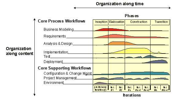
The Unified Process repeats over a series of cycles, where each cycle concludes with a product release. Each cycle consists of four phases: inception, elaboration, construction, and transition.
The new product release includes the requirements, use cases nonfunctional requirements, test cases, the architecture and the visual models (artifacts modeled by the UML). Furthermore, for the developer to carry out the next cycle efficiently, the developers need all the representations of the software product:
- A use case model with all the use cases and their relationship to users.
- An analysis model, which has two purposes: to refine the use cases in more detail an to make an initial allocation of the behavior of the system to a set of objects that provides the behavior.
- A design model design model that defines (a) the static structure of the system as subsystems, classes, and interfaces and (b) the use cases realized as collaborations among the subsystems, classes, and interfaces.
- An implementation model, which includes components (representing source code) and the mapping of the classes to components.
- A deployment model, which defines the physical nodes of computers and the mapping of the components to those nodes.
- A test model, which describe the test cases that verify the use cases.
- A representation of the architecture.
Phases within a Cycle
Each cycle is divided into four phases as said above. Within each phase there may be iterations and the resulting increments. Each phase terminates in a milestone, where the milestone is defined by the availability of a set of artifacts (certain models or documents have been brought to a orescribed state).A typical iteration goes through all the five workflows - requirements, analysis, design, implementation, and test. During the inception phase the following questions should be answerd:
- What is the system primarily going to do for each of its major users?
- What could an architecture for that system look like?
- What is the plan and what will it cost to develop the product?
In the elaboration phase most of the use cases are specified in detail and the system architecture is designed. The relationship between the architecture of a system and the system itself is paramount. The architecture is expressed as views of all the models of the system, which together represent the whole system. This implies that there are architectural views of the use-case model, the analysis model, the design model, the implementation model, and the deployment model.
During the construction phase the product is built.
The transition phase covers the period during which the product moves into beta release. This phase involves activities s.a. manufacturing, training customer personell, providing help-line assitance, and correcting defects found after delivery.
UML in a Nutshell
The UML is composed of nine diagrams:- Use case diagram: Use cases are text descriptions of the interaction between some outside actors and the computer system. Use case diagrams are graphical descriptions of the relationship between actors and use cases and between a use case and another use case. See also "Four Roads to Use Case discovery" by Gary A. Ham
- Sequence diagram: Sequence diagrams and collaboration diagrams show the internal working of a use case scenario. They present a dynamic view of a system, showing how messages pass between objects to satisfy a use case.
- Collaboration diagram
- Statechart diagram: Statecharts and activity diagrams are also part of the dynamic view of a system. They concentrate on transition from one state to another.
- Activity diagram
- Class diagram: Class diagrams are geared toward the static view of the system. They show the different classes and their associations.
- Object diagram
- Component diagram: Help move the system from a collection of fine-grained objects to a collection of coarser-grained components, and help show how these components relate to one another.
- Deployment diagram: Show how components of the system will be deployed to different physical nodes, or machines, in the production environment.